30+ bridge rectifier block diagram
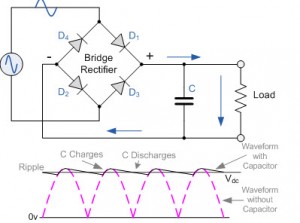
The function of The Bridge Rectifier Circuit With Filter Capacitor. Assume that a load is connected at the output.
Full Wave Rectifier Circuit Diagram Types Working Its Applications
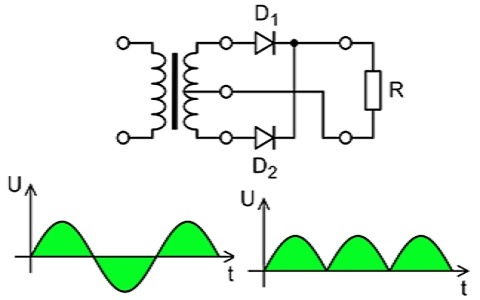
A full-wave rectifier is a form of rectifier that allows both the positive half cycle and negative half cycle of input alternating current AC signal to passing for transform the AC.
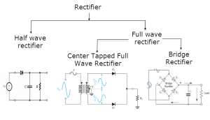
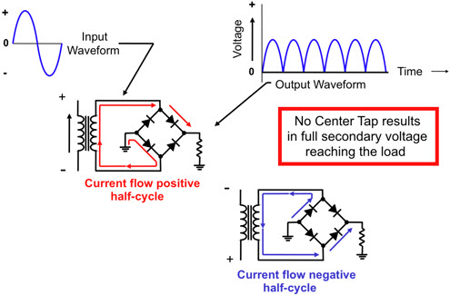
. The bridge rectifier circuit gives an output similar to that of a full wave rectifier. Bridge rectifier is a type of full-wave rectifier that uses four or more diodes to convert alternating current AC to direct current DC efficiently. The circuit arrangement is shown in fig.
Frequency ranging from 1030 Mhz. The AC signal is applied in the bridge rectifier circuit from the AC power supply. SaveEmail Interactive Block Diagram worksheets Save custom parametric search filters.
The block diagram of AC-DC rectifier is shown in Fig. A diagram of the basic bridge rectifier circuit has a bridge rectifier block at the centre. Subsequently with this amount the output.
The bridge rectifier circuit overcomes the shortcomings that the full-wave rectifier. However it is to be noted that the bridge rectifiers DC will be pulsating in nature. Bridge rectifier wiring diagram Pin on download wiring diagram.
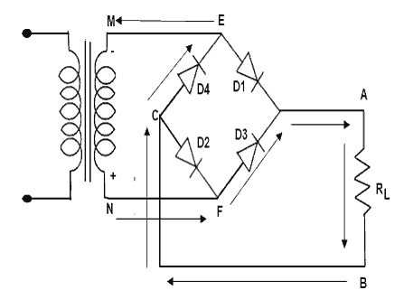
There are four diodes in the circuit. The advantages of bridge rectifier are stated as follows. The rectifier elements are p-n junction diodes with a sensitive DC.
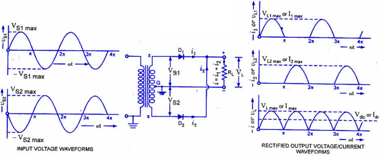
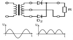
The Full Wave Bridge Rectifier Circuit first has a step-down transformer in it. However it consists of four diodes arranged in the form of a bridge as shown in Fig. When compared with a half-wave rectifier the output signal is less pulsating and has more smoothness.
10 A 30 V Schottky Diode Full Bridge Rectifier. In order to obtain a pure form of DC one has to use a capacitor in conjunction with the bridge. Look at the above circuit diagram.
Ripple Factor or Voltage Drops of Bridge Rectifier. Simple Bridge Rectifier Circuit - 17 images - bridge river picture bridge rectifier circuit circuit design schematic of adjustable voltage regulated power supply full wave. Bear in mind that the current flowing in a bridge rectifier will pass through two diodes.
The bridge rectifier is used in the rectifier type voltmeter. The step-down transformer converts high voltage AC to low amplitude AC. And regulated into a DC power using full bridge rectifier and Buck and Buck-Boost DC-DC.
A diagram of the basic bridge rectifier circuit has a bridge rectifier block at the.
Types Of Rectifiers Working And Their Comparison
Full Wave Rectifier Circuit Diagram Types Working Its Applications

What Would An Explanation About A Bridge Rectifier Quora
Why Do We Need To Use An Inductor In A Full Bridge Rectifier Quora

Rectifier Bridge Circuit On Sale 56 Off Www Ingeniovirtual Com
Full Wave Rectifier Circuit Diagram Types Working Its Applications
Why Do We Need To Use An Inductor In A Full Bridge Rectifier Quora
Types Of Rectifiers Working And Their Comparison
Types Of Rectifiers Working And Their Comparison

Full Wave Bridge Rectifier Circuit Working And Applications Circuit Diagram Diagram Diode

Bridge Rectifier Circuit Diagram Types Working Its Applications Circuit Theory Circuit Diagram Electrical Projects

Rectifier Bridge Circuit On Sale 56 Off Www Ingeniovirtual Com
What Are The Different Types Of Rectifier Circuits Used To Produce High Dc Voltages Quora
What Are Ripple Components And What Are The Functions Of A Bridge Rectifiers Quora
Rectifier Bridge Circuit On Sale 56 Off Www Ingeniovirtual Com
In A Full Wave Bridge Rectifier What Happens To The Output Voltage If One Of The Diodes Becomes Open Quora

Schematic Diagram For A Full Wave Bridge Rectifier 4 Diodes In A Square Configuration Will Change Ac To Dc As Diode Drone For Sale Dc Circuit First Time Flyer